|
The LIVE Spectrum analysis pages are active!
Click here
 < Current latest plot.
Click
for full size.
< Current latest plot.
Click
for full size.
NB: Other links to internal and external sites are at
the
bottom of this page.
Introduction
The radio detection of aurora and meteors is made possible at my QTH in
Plymouth, UK by listening to the carriers of distant Band 1 TV stations.
The frequencies I've chosen are 48.250MHz (European TV channel "E2")
and 59.258 MHz (channel R2-6p).
I use DL4YHF's excellent and dead
cool Spectrum Laboratory v2.5b6 fed from the audio output of two Icom PCR-1000s in USB mode,
which are tuned to zero-beat frequencies of 48.249485 and 59.258330 MHz. The antenna is a
dipole, in the loft, tuned to approx 50MHz, with a 9dB wideband dual-output amplifier.
Any
other frequencies that gives good returns at your location will also do just as
well. See the links below for various TV frequency lists. More detail
about the setup can be found here
[
How-to setup a Radio Meteor Obs. Station]
Several European TV stations are present on this frequency that cannot be
received by ground wave propagation. Any other mode of propagation that bounces
the signal in my direction is detectable, such as sporadic E, meteor reflection,
auroral reflection and (maybe possibly?) reflection from high-flying aircraft or
even spacecraft. I've seen signals that appear to be the later, though proving
that theory is difficult! Doppler shifts of a few tens of hertz, as caused by
aircraft, have been well observed by others and myself by monitoring HF
broadcast carriers, but I'm not sure about the satellites. There may be other
reasons for fast changing carriers sweeping through the detection range...
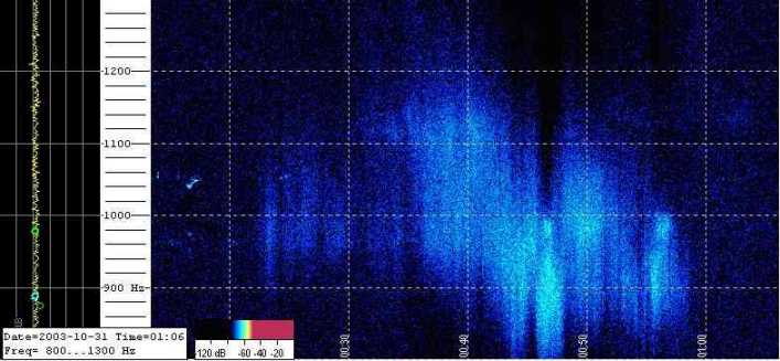
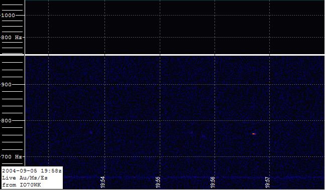
The image above is a very good example of an auroral signal. It was recorded
on 31st Oct 2003 between 0010 and 0110 GMT, during the second night of big
aurora over the UK in 2 days. Visible in the sky over Plymouth were various red glows and an
arc of white stretching overhead. The signal is spread out due to the rapid
Doppler shift caused by the charged particles in the auroral curtain rapidly
moving. Also, several TV carriers which are a few hundred hertz apart are being
reflected simultaneously, making the Doppler effect appear bigger than it really
is.
|
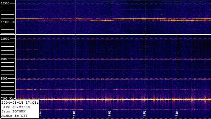
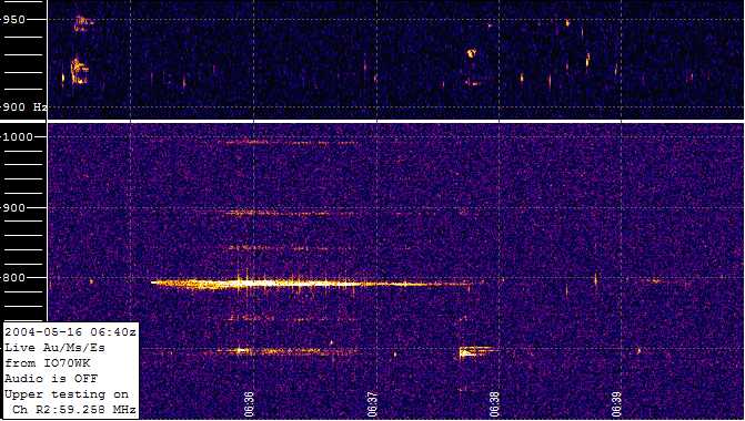
This is an example of how a Sporadic E (Es) opening looks. Signal levels
can be extremely high, and the receivers' AGC levels are often compressed.
Here, two carriers only 6 Hz apart are visible on Channel R2. Also visible
in the lower trace are the typical 50Hz harmonic lines from the analogue
TV transmitter in Sweden.
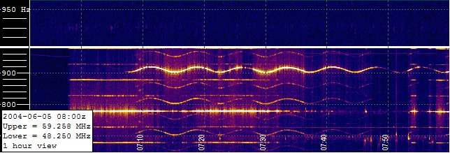
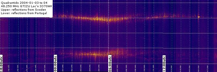
Another Sporadic E Opening, showing how the signals can stop
coming from one direction or location, and turn to another. Here TVE Spain
gives way to RTP Portugal. The wobbling Portugese signal is caused by the transmitter frequency drifting in a 10 minute
cycle, due to poor TX frequency control or local mains frequency instabilities at the TX site.
For daily update announcements about this site, click the weblog link on the
live page. Any other announcements of significance will be made in the
rec.radio.amateur.space
and uk.sci.astronomy newsgroups, and in the
Meteorobs mail list.
Andy.
|