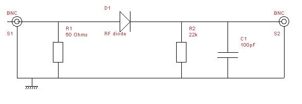
For a radio telescope operating as a total power receiver, it is possible to use readily available modules for everything except the detector. The detector itself can be a very simple circuit, but due regard to layout and construction is essential due to the high frequencies involved.
The circuit could be constructed on veroboard or similar, but for best results a rectangle of copper clad board should be used. The largest area is left to provide a good ground, and two strips about 2 or 3 mm wide are excised from the copper to leave a track of the same width between them. This track is cut about a quarter or a third from the left- hand end - the diode will be soldered across the gap. The other components are soldered from the narrow strip to the large grounded area.
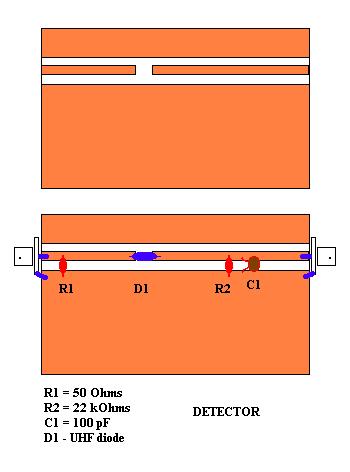
An alternative construction method using a sheet of copper or a piece of copper clad board in the lid of the die-cast box plus a copper rod or thick wire could be employed.
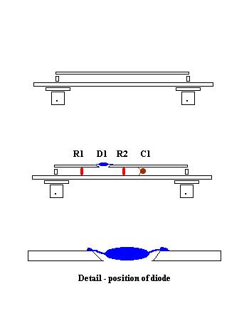
Please note that all components should be of a small size, particularly the capacitor. The latter should be around 2 or 3 mm in size to avoid associated inductance. The diode may be any suitable RF type that is capable of operating at 1 to 2 GHz. All leads must be kept short and curves avoided as these will act as inductances at this frequency. All soldering must be neat and tidy. The diode should be fitted last as this is the most heat sensitive component.